 English
 عربى

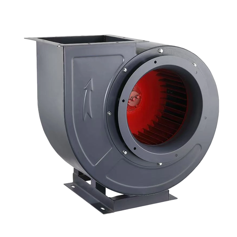
When sizing a centrifugal fan for a pneumatic conveying line, a dust collection duct run, or a high-resistance ventilation duty, the number that matters is not the motor kW — it is the airflow at the pressure your system actually needs. A 7.5 kW motor driving a fan that runs at only 40% of its pressure rating wastes energy and money; the same motor paired with the right impeller geometry delivers the duty with margin to spare.
01Quick Technical Summary
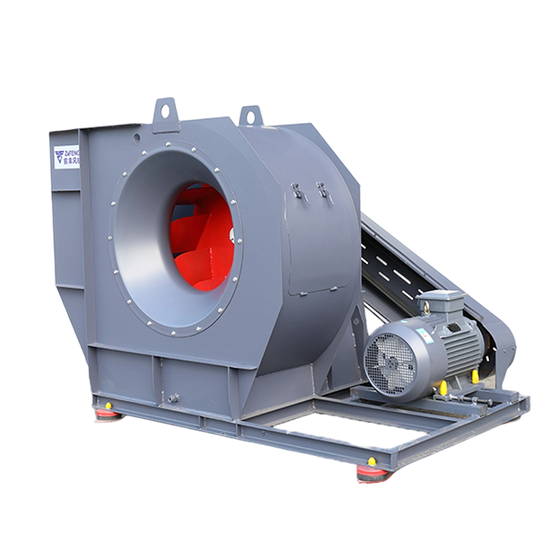
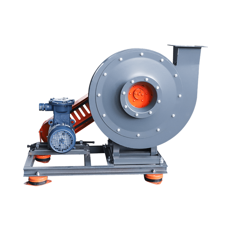
Figure 1. The 6-30 5.4C 7.5KW unit at Zhejiang Zifeng's Daxi plant, showing the defining features of the C-type belt drive: the fully enclosed belt guard, the TEFC motor mounted on a slotted base plate for centre-distance adjustment, the welded steel scroll with its 90° rectangular discharge flange, and the red spring vibration isolators that isolate transmitted vibration from the building structure.
02Decoding the Model Number
Understanding "6-30 5.4C" tells you more than any marketing phrase, so it is worth breaking down.
2.1 What "6-30" means
The 6-30 designation identifies the fan series by its aerodynamic family. The first number is the series reference — the base geometry the impeller, side plate and scroll were designed around. The second number, 30, indicates the design pressure coefficient of the series. Series numbers in the 20s–30s denote high-pressure, multi-blade designs; the higher the number, the steeper the pressure characteristic.
The practical consequence is important: a 6-30 fan produces substantially more static pressure at a given flow than a general-purpose 4-72 series fan of comparable power. That is exactly why 6-30 units dominate grain handling, seed processing, sawdust extraction, coal dust collection and boiler induced-draft duties worldwide.
2.2 What "5.4" means
The number after the series code is the impeller diameter expressed in decimetres (1 unit = 100 mm). A 5.4 size therefore means a 540 mm diameter impeller, giving an inlet eye diameter of approximately 300 mm.
Impeller diameter is the single most powerful sizing variable in the fan world, because flow scales roughly with the square of diameter and pressure with the square of speed:
Q ∝ D² × n        (airflow)
P ∝ n²             (total pressure)
Doubling the impeller diameter multiplies airflow by roughly four. It also means that one frame size can cover an enormous operating envelope, simply by changing the sheave ratio. That is the core advantage of the belt-driven arrangement described below.
2.3 What "C" means — and why it matters for your quote
Why C-type for a 7.5 kW medium pressure fan? Three practical reasons:
- Speed flexibility. A sheave swap on site moves the fan up or down the curve without changing the motor. This is the single most valuable capability during commissioning on a real duct network.
- Isolation. The motor sits outside the airstream, clear of the hot, dusty gas — no motor derating, no contamination of the winding, far better bearing life.
- Maintenance. Belts and sheaves are consumables that can be changed in minutes without dismantling the scroll. On an A-type direct-drive unit, replacing the motor means pulling the impeller.
The 5.4C therefore pairs a 7.5 kW motor with a 540 mm impeller on a belt drive, giving a machine that is genuinely medium pressure within the 6-30 family.
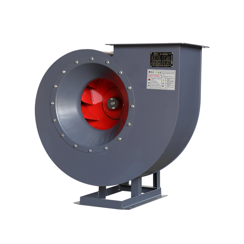
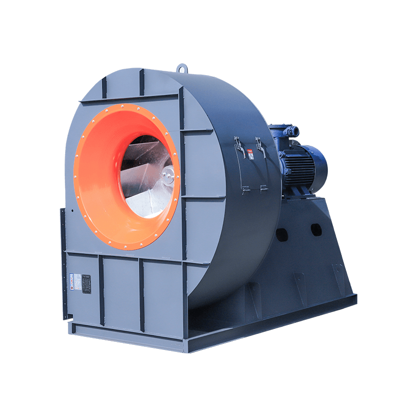
Figure 2. Front view of the Zifeng-built fan, showing the double-curve suction bellmouth with its bolted inlet ring, the 12 backward-curved blades of the welded steel impeller visible through the inlet eye, the rectangular discharge flange at 90°, and the ZIFENG 紫丰风机 nameplate on the scroll. A double-curve inlet like this is a primary quality indicator — the curved bellmouth avoids the 30–50 Pa of suction loss that a flat plate inlet imposes on every operating hour.
03Performance Parameters
3.1 The 6-30 series reference table
The following are the published 6-30 series performance figures at the standard reference conditions (air at 20 °C, atmospheric pressure 101,325 Pa, density 1.2 kg/m³, relative humidity 50%). Use them as a selection cross-check; the exact curve for a given impeller diameter is confirmed against the manufacturer's certified test data at order stage.
6-30 series — direct drive (A type), 2900 r/min
6-30 series — belt drive (C type)
Reference conditions: air at 20 °C, 101,325 Pa atmospheric pressure, density 1.2 kg/m³, relative humidity 50%. Figures are indicative for series cross-selection; certified curves are issued per order.
3.2 The 6-30 5.4C 7.5 kW duty point
The 5.4 size sits between the 5 and 6 frames on the C-type belt-drive curve. With a 7.5 kW motor, the 5.4C is the configuration selected where the system needs roughly 4,000 – 6,500 m³/h at 2,200 – 3,600 Pa of total pressure.
Important engineering note. The 7.5 kW rating is the shaft input power available. The air power at the operating point must sit at roughly 70–85% of it for the fan to run efficiently and keep motor temperatures within limits. If your duct resistance is much higher than the figure above, the correct response is a larger frame or a higher-resistance impeller — not simply a bigger motor.
3.3 Reading the curve
Three numbers define any fan point:
- Airflow (Q, m³/h) — the volumetric rate through the inlet.
- Total pressure (P, Pa) — the sum of static and velocity pressure at the outlet.
- Power (N, kW) — the shaft power required at that point.
On a 6-30 curve the pressure line rises steeply as flow falls. That steepness is a feature for pneumatic conveying: a conveying line needs high pressure to lift material and maintain a solids suspension through the pipe, and the system will naturally find its own equilibrium on the curve.
The practical rule for a pneumatic conveying installation is to pick a fan that can hold the required airflow at the required static pressure with the operating point sitting roughly 10–15% to the right of best efficiency rather than at the peak itself. The peak is for a laboratory; real ducts have losses.
04Construction and Design Details
4.1 The impeller
The 6-30 impeller is a welded steel fabrication, not a cast or stamped pressing:
- 12 backward-curved blades of forward-curved multi-blade profile, mounted between the front plate and the rear plate.
- The front plate is a double-curve (hyperbolic) profile, which is the key to the series' high-pressure capability. The double-curve inlet accelerates the incoming flow smoothly and reduces the inlet loss coefficient compared with a flat-front single-curve design.
- Stainless steel / alloy steel / special alloy blade options are available for abrasive or corrosive duty.
The blade count matters: 12 blades is a compromise. More blades approach true forward-curved behaviour — high pressure, lower flow, higher efficiency at high pressure, but with a narrower operating range and more risk of stall. Fewer blades give a flatter curve and better high-flow behaviour. The 6-30 uses 12 to sit in the sweet spot for conveying duties.
4.2 The scroll (volute)
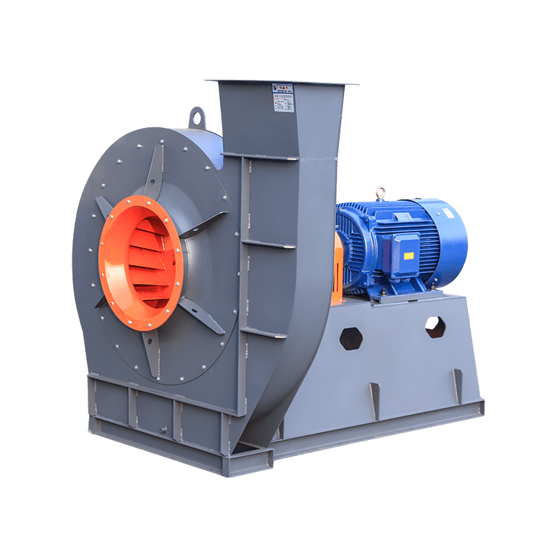
The casing is a welded steel scroll with a 90° rectangular discharge flange — a deliberate choice, because:
- A rectangular outlet bolts directly onto standard rectangular ducting and baghouse flanges without a transition piece.
- The transition from round to rectangular happens inside the scroll where the gas is already turbulent and the losses are unavoidable.
- Standard rectangular flange dimensions mean the fan drops into existing ductwork without modification.
Both left-hand and right-hand rotation are available, and the discharge can be oriented to suit the incoming duct layout.
4.3 The inlet and inlet ring
The suction side uses a double-curve bellmouth inlet cone with a bolted inlet ring. The bellmouth is a genuine engineering feature rather than a flat plate:
- A smoothly curved inlet reduces the sudden expansion loss that occurs when air is drawn in from a flat surface.
- The bolted inlet ring allows the inlet diameter to be adapted by changing the ring — a standard field modification to trim airflow without changing sheaves.
- The inlet flange and the discharge flange are both machined and bolted, so duct connections are leak-tight.
4.4 The drive train
The spring vibration isolators under the frame are worth noticing. They are not decoration: they isolate the fan's transmitted vibration from the building structure, which reduces noise bleed into adjacent work areas and protects the concrete from fatigue cracking.
4.5 Manufacturing process at Zifeng
Zhejiang Zifeng Fan Co., Ltd. operates a 20,000 m² plant in Daxi Town, Wenling, Zhejiang with registered capital of CNY 10 million, over 50 staff and annual output valued at CNY 50 million. The relevant machinery for a fan of this class:
- 2 × laser cutting machines for the plate and blade profiles — accurate, repeatable blade geometry and clean laser-cut edges on every part.
- 10 × CNC rotary/spinning machines for the scroll shells — a spun scroll gives a far smoother internal surface and better roundness than a welded polygon, reducing leakage and turbulence.
- Large hydraulic presses and vertical lathes for flanges, bearing housings and heavy structural parts.
Every impeller is dynamically and statically balance corrected before dispatch, which is what keeps vibration low and bearing life long. A 540 mm wheel running at 1,450–2,400 r/min will find any imbalance very quickly — balancing is not optional at this size.
05Installation, Commissioning and Maintenance
5.1 Installation
- Foundation. Mount the unit on a rigid level foundation, using paired shims to level the base. For a 5.4C at roughly 350 kg, a reinforced concrete plinth or a properly engineered steel support is required.
- Duct support. The ductwork must be supported independently. Never hang the weight of the duct on the fan outlet flange — this will distort the scroll, which is a thin welded fabrication and is very sensitive to out-of-plane loading.
- Isolation. Ensure the anti-vibration mounts are not short-circuited by rigid ductwork, conduit or grounding straps that bridge the frame. The whole point of the isolators is lost if the duct ties the fan back to the building.
- Inlet clearance. Keep the inlet cone at least one inlet diameter clear of walls and obstructions. A fan drawing from a starved inlet produces noise, vibration and a severely degraded curve.
- Rotation check. Before connecting the drive, briefly jog the motor and confirm the impeller rotates in the direction matching the scroll. On a C-type unit the rotation is determined by the sheave position and belt alignment, not by the motor terminals alone.
5.2 Commissioning and speed setting
This is where the C-type drive pays for itself:
- Start the fan with the system in place and measure actual airflow and pressure.
- Compare against the design point.
- Adjust by changing the sheave ratio, not by moving the motor. The motor base plate is slotted for centre-distance adjustment only — it exists so the belt can be tensioned, so that the drive ratio stays fixed.
- Record the final sheave diameters and belt tension in the commissioning file, so future maintenance uses the same setup.
Do not over-run the curve. Running well below the design flow on a high-resistance line wastes power and risks stall; running far above it means the system resistance has changed and the fan should be re-selected rather than pushed.
5.3 Routine maintenance schedule
5.4 The five failure modes to watch
1. Belt wear and slip
The most common failure on a C-type unit. Symptoms: rising current at constant flow, visible fraying, a burnt rubber smell. Replace matched belts in sets and re-tension.
2. Bearing failure
Caused by misalignment, over-lubrication (a very common and under-diagnosed cause) or contaminated grease. Grease the correct quantity only.
3. Imbalance
Usually caused by material build-up on the blades, or by a fan operated at an angle. Clean the impeller; do not attempt to re-balance a dirty wheel by adjusting weights.
4. Scroll leakage
Cracks at the outlet flange or around the inlet ring caused by duct strain or thermal cycling. Seal and check flange bolting.
5. Overload and motor overheating
Usually the consequence of operating far outside the curve — a static-pressure problem, not a motor problem. Correct the system resistance.
06Applications
The 6-30 5.4C 7.5 kW occupies the classic middle ground of medium pressure, medium flow, continuous duty.
6.1 Pneumatic material conveying
Grain, seed, cotton, sawdust, wood chips, plastic pellets, soybean, rice husk and other granular or powder materials. The 6-30's steep pressure characteristic maintains conveying velocity through long, high-resistance pipe runs, and the double-curve inlet gives the required flow at low suction loss. This is the design intent of the series.
6.2 Dust collection and filtration
Baghouse, cyclone and electrostatic precipitator induced draft. A 5.4C at 7.5 kW suits mid-size baghouses handling a few thousand m³/h. The key benefit is the ability to develop the several hundred Pa of differential pressure that a fabric filter or a dust-loaded cyclone demands — a job that general-purpose axial or low-pressure forward-curved fans cannot do economically.
6.3 Boiler induced draft
As a Y6-30 build, the same impeller family serves boiler ID fans, where the impeller material and the maximum medium temperature rating (up to 250 °C with a heat-resistant build) are specified for hot flue gas.
6.4 Process ventilation and drying
Drying lines in grain, feed, chemical and pharmaceutical production, where a controlled extraction flow at a controlled negative pressure is required.
6.5 Mechanical ventilation and exhausting
Workshop and warehouse extraction, kitchen and canteen exhaust (via the CF series), and general industrial ventilation where the system resistance is higher than a light-duty fan can cover.
6.6 OEM and equipment builder integration
As a component inside a dust collector package, a pneumatic conveying skid or a boiler package — which is how most export orders for this class of fan actually arrive.
07Material, Motor and Configuration Options
7.1 Material options
The impeller material can be changed while keeping the same frame, which is how one 6-30 machine serves both a grain mill and a coal-fired boiler.
7.2 Motor options
7.3 Options to specify at order
- Rotation: right-hand or left-hand
- Discharge orientation
- Sheave diameter sets for field speed adjustment
- Inlet ring diameter for airflow trimming
- Anti-vibration base frame (standard) or seismic / anchor-bolted frame
- Belt guard: fully enclosed mesh guard (standard) or perforated
- Drain plug on the scroll for condensate removal
- Inspection door with quick-release latches
- Special coatings, English nameplates, CE marking and Declaration of Conformity
08Why Engineers Choose the 6-30 5.4C 7.5 kW
Ready to price your 6-30 5.4C 7.5KW fan?
Send us your airflow, pressure and duty details and our engineering team will return a correctly sized selection with the certified performance curve, sheave recommendation and an FOB quotation.
Contact Zhejiang Zifeng Fan Co., Ltd.