Home / News / Industry News / ID Fan vs. FD Fan in Boiler Systems: What's the Difference and How to Choose
ID Fan vs. FD Fan in Boiler Systems: What's the Difference and How to Choose
If you have ever asked a boiler supplier for "two fans" and got a quote back where one of them was roughly the same physical size as the other, the supplier was guessing. The FD fan (forced-draft, blowing air into the furnace) and the ID fan (induced-draft, pulling flue gas out) handle two completely different duties, and the ID fan is almost always the larger, more expensive and more carefully specified of the two.
This article is the engineering version of that observation. It is written for the buyer, EPC engineer or boiler-house operator who wants to know which fan does what, why the numbers on the data sheets look so different, and how to specify both correctly on the same RFQ.
TL;DR - The FD fan handles cold, clean combustion air on the upstream side of the furnace. The ID fan handles hot, dirty flue gas on the downstream side. The ID fan is built for temperatures up to 250 °C (or more), with a water-cooled bearing housing, wear-resistant blades and a shaft seal that stops both gas out and air in. For a 20 t/h gas-fired boiler the ID fan moves about 1.8 × the FD volume and its motor is sized for the cold-start density- on a cold start the same fan draws about 40 % more power than at design. Zifeng makes the dedicated Y5-47 (≤ 250 °C, water-cooled bearing base) and YN5-47 (160 - 200 °C, air-cooled) for the ID side, and the 4-72 / 9-19 / 9-26 / 8-09 / 9-12 catalogue for the FD side.
1. The two-fan trick every boiler has
A solid-fuel or liquid-fuel boiler needs three things from its fans: combustion air, removal of the resulting flue gas, and a small controlled negative pressure in the furnace so the boiler does not "puff" hot gas into the room through every door and inspection port. The configuration that delivers all three is called balanced draft: one fan on the upstream (clean) side and one on the downstream (dirty) side, working against each other to keep the furnace at a small fixed negative pressure - typically -20 to -50 Pa relative to the boiler house.
Almost every package boiler, every industrial coal-fired boiler, every CFB, every waste-to-energy plant and utility boilers use this pattern. The fans are not interchangeable: a backward-aerofoil fan that is on the FD side will overheat, corrode, vibrate itself apart and shed its blades if you put it on the ID side of a coal-fired boiler. The two fans have to be specified to the duty, not to each other.
2. Where each fan sits in the gas path
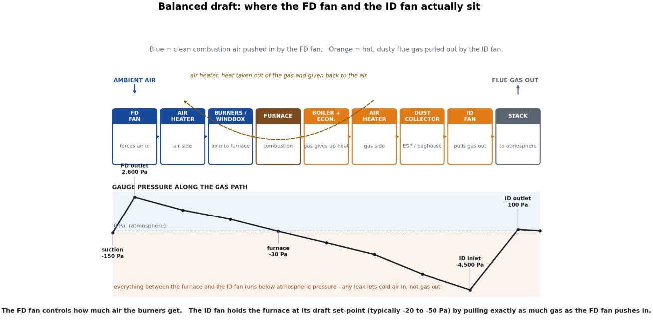
The figure below is the simplified gas path of a fuel-fired boiler. The colour matters: blue is the clean combustion air being pushed in, orange is the hot flue gas being pulled out. Everything between the FD fan outlet and the ID fan inlet is at above-atmospheric (furnace and windbox) or below-atmospheric (everything after the boiler bank) pressure. The plot below the gas path is the gauge pressure along it.
Figure 1. The blue side is clean air being pushed in. The orange side is hot flue gas being pulled out. The dashed yellow arc is the air heater - the same air heater on both sides, transferring heat from the gas to the combustion air. The plot below the path is the gauge pressure at each point: the FD fan raises pressure from -150 Pa (suction) to about +2,600 Pa, the gas drops in pressure through the boiler and dust collector to about -4,500 Pa at the ID fan inlet, and the ID fan lifts it back to near atmospheric before the stack. Anything that leaks in the orange section leaks cold air in, not gas out - that is the single important fact about a balanced-draft system.
Two practical points the figure does not show:
Most plants actually have a third fan - the primary air (PA) fan - on a coal-fired boiler, blowing hot air into the pulveriser or under the bed. The PA fan duty is similar to the FD fan duty (clean air, but higher pressure - often 10 - 15 kPa on a PC boiler), and a Chinese-supplier RFQ will sometimes roll it into the same "boiler fan" line. It deserves its own line in the BOM.
A secondary air (SA) fan shows up on some large boilers, blowing air over-bed or into the over-fire air ports. Same FD-fan family, smaller duty.
3. The 12 specification differences
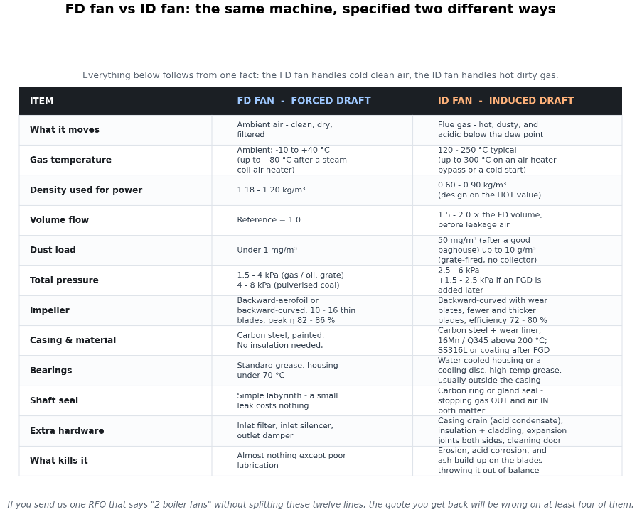
If you send a supplier one RFQ that says "two boiler fans", the quote you get back will be wrong on at least four of the twelve lines below. The supplier does not know whether you are putting them on the right side, and the sales engineer will usually quote the more expensive (ID-fan) spec on both to be safe. That is a fast way to overpay.
Figure 2. The same machine specified two different ways. Most of the differences trace back to one fact: the FD fan handles cold clean air, the ID fan handles hot dirty gas.
Five of the twelve are worth dwelling on, because they are the ones that cause real failures in the field:
Density for power calculation. Use 1.18 - 1.20 kg/m³ for the FD fan, 0.60 - 0.90 kg/m³ for the ID fan. Using 1.2 for both (a common copy-paste error) undersizes the ID motor by about 30 %.
Volume flow. A typical 20 t/h gas-fired boiler has an FD fan moving ~17,000 m³/h and an ID fan moving ~32,000 m³/h, a ratio of 1.8 : 1. This is not the same fan with the same impeller trim.
Dust load. "Clean" FD-side air carries well under 1 mg/m³ of dust. "Clean" ID-side flue gas after a baghouse still carries 20 - 50 mg/m³. Without a dust collector, grate-fired flue gas carries 5 - 10 g/m³ - that is the impeller-blade lifetime on a clock.
Bearings. An ID fan with an uncooled bearing housing will cook its grease above about 130 °C. The ZIFENG Y5-47 uses awater-cooled integral bearing basefor that reason. Smaller YN5-47 boilers (160 - 200 °C) get away with an air-cooled motor seat and a heat-insulating coupling spacer.
Shaft seal. On the FD side, a small leak is harmless. On the ID side the seal has to stop hot, possibly acidic, gas from leaking outandstop cold air from being sucked in (cold air dilutes the flue gas, ruins the draft setpoint, and condenses moisture into acid in the casing).
Send us both duties on one RFQ. We will quote the FD fan on the clean-air spec and the ID fan on the hot-gas spec, and we will tell you which ZIFENG platform we are starting from on each side. Send the duty point, the gas temperature, the dust load, the altitude and any future FGD retrofit plan. mia@zifengfan.com
4. Why the ID fan moves ~1.8× the volume
Three numbers stack up: more mass, same stoichiometry, hotter gas.
More mass. Combustion adds about 11.6 Nm³ of wet flue gas for every 10.6 Nm³ of combustion air, because the hydrogen in the fuel carries its own volume as water vapour.
Excess air. Real burners do not run at stoichiometric. 5 - 15 % extra air is needed for complete combustion and acceptable CO / NOx. The ID fan sees that extra volume too.
Temperature. Combustion air enters the boiler at 25 °C. Flue gas leaves the air heater at 120 - 200 °C. The same mass of gas occupies about 1.5 - 1.7 × the volume at the higher temperature (the standard ideal-gas relation, which is exact enough for fan selection here).
5. A worked example: 20 t/h gas-fired boiler
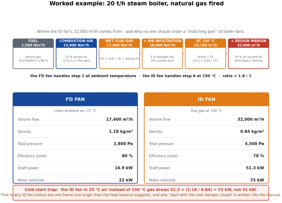
The chain below is what the heat balance of a 20 t/h gas-fired package boiler looks like when you write down every step instead of jumping from "burner rating" to "fan duty". The numbers are the actual numbers, not round ones, and they are the numbers you should be checking when a supplier sends you a fan selection report.
Figure 4. The flow chain on top is the audit trail. The two cards at the bottom are the answer: the FD fan is a 22 kW backward-aerofoil 4-72-class machine, the ID fan is a 75 kW Y5-47-class machine with a water-cooled bearing base. The red callout is the cold-start trap - read the next section before you sign the motor order.
The audit points worth pulling out of the figure:
The fan laws are exact here. For a given speed and a given system-curve shape, both the fan curve and the system resistance curve scale linearly with gas density. So if the system resistance at design is 4,500 Pa at 150 °C (ρ = 0.84), the same fan at the same speed in 25 °C air (ρ = 1.18) sees a system resistance of 4,500 × (1.18 / 0.84) = 6,320 Pa, and the operating point moves along the fan curve to deliver the same volumetric flow at the higher pressure.
Same volume, 1.4× the power. Volumetric flow is unchanged (system-curve intersection in Q stays put), pressure rises by 1.4×, so shaft power rises by 1.4×: from 51.3 kW to 72.0 kW.
The 75 kW motor is on the line. A 55 kW motor (sized on hot-duty power alone) trips on cold start. That is what the red banner in the figure is warning about.
6. The cold-start trap that picks the ID motor
This is the single common cause of "the ID fan motor keeps tripping on light-up" we see on new boilers.
On a cold boiler the casing, ductwork and dust collector are full of ambient air, not hot flue gas. The damper at the ID fan inlet is usually set closed to reduce the cold-start inrush, but as soon as the burner lights and the damper starts opening, the density of the gas in the fan drops from 1.18 kg/m³ to 0.84 kg/m³ over a few minutes. The fan power falls with it. The problem is thefirst 30 seconds, when the fan is seeing 1.18 kg/m³ air against a system curve sized for 0.84 kg/m³ gas.
Two rules that fix this:
Size the ID motor for the cold-start condition - which for a 150 °C design case means multiplying the hot-duty shaft power by 1.4 (for a 150 °C ΔT) or 1.7 (for a 250 °C ΔT). For our 20 t/h example the 51.3 kW hot-duty shaft power becomes 72 kW cold-start, and the next standard motor frame up is 75 kW.
Start the ID fan with the inlet damper closed and open it as the gas temperature rises. This is the line in the manual that the installer skips on the commissioning and the operator skips on every cold start after that, until a winter morning when the motor trips and someone finally reads the page.
Not a ZIFENG problem to solve alone. On the few applications where the ID fan is started with the damper open (some VFD-driven systems, some boilers without a damper), the motor must be sized for the cold-start power. A VFD does not save you on a cold start - it makes it worse, because the reduced speed puts the operating point at the wrong place on the fan curve. The right way to use a VFD on an ID fan is for oxygen trimming and turndown, with the standard motor sized for the cold case.
7. Which ZIFENG series goes where
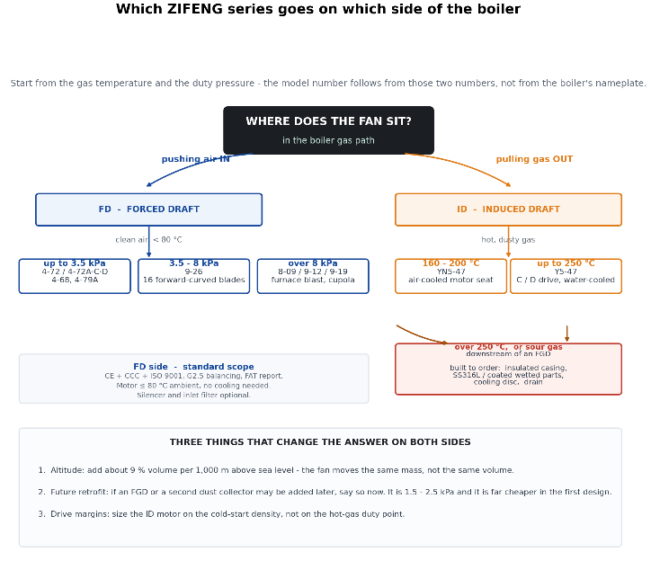
Mapping the matrix back to our catalogue, and only to our catalogue. The figure is a decision tree, not a comparison - it tells you where to start the selection, not which is "best".
Figure 5. Start from the gas temperature (ID) and the duty pressure (FD). The model number follows. The "built to order" branch covers > 250 °C and any gas downstream of an FGD - it is still inside our scope, just not a catalogue line.
Three things that change the answer on both sides - the box at the bottom of the figure:
Altitude. The fan moves the same mass, not the same volume. At 2,000 m above sea level the air density is about 18 % lower than at sea level, so for the same combustion-air mass you need about 18 % more volumetric flow. Get this wrong on the FD side and the burner runs fuel-rich; get it wrong on the ID side and the draft setpoint is unachievable. The ZIFENG selection sheet already adds about 9 % volume per 1,000 m, but you still have to tell us the altitude on the RFQ.
Future retrofit. If the plant may add an FGD, a second dust collector, or a waste-heat boiler downstream in the next five years, say so on the RFQ. Each of those adds 1.5 - 2.5 kPa, and it is much cheaper to oversize the ID fan impeller and the motor frame now than to retrofit later.
Drive margins. Already covered in section 6, but worth restating: size the ID motor on the cold-start density, not on the hot-gas duty point.
8. Specification checklist for your next boiler RFQ
Twelve items to put on the RFQ. We can quote from a subset, but the more you give us the smaller the safety factor we have to add.
Boiler steam capacity (t/h) and steam pressure / temperature.
Fuel type and LHV. Excess-air target (typically 10 - 15 % for gas, 15 - 25 % for coal, 20 - 30 % for biomass / waste).
Altitude above sea level.
FD-side: combustion-air temperature (ambient, or preheated by a steam-coil air heater), inlet filter / silencer requirement, total pressure target at the burner inlet.
ID-side: flue-gas temperature at the ID fan inlet, dust load (mg/m³ or g/m³) at design and at the worst-case dirty-baghouse condition, total pressure target at the stack inlet including the dust collector ΔP and any planned FGD.
Acid-gas content (SOx, HCl, moisture) and whether the gas is below the acid dew point at any operating condition. Drives material selection for the ID casing.
Drive type preference: direct-coupled, belt-driven, or with a fluid coupling. VFD or fixed-speed. Soft-starter or DOL.
Motor standard: IEC or NEMA. Insulation class, IP rating, efficiency class (IE2 / IE3 / IE4).
Certifications required: CE, CCC, EAC, ATEX zone, UL / CSA.
Acoustic limit at 1 m (dB(A)).
Site constraints: ambient temperature range, humidity, available duct connections, foundation drawing.
Service factor: how dirty the gas is, how often the plant runs at part load, whether the boiler is base-load or two-shift.
Ready to send the RFQ?The four numbers we need to start: steam capacity, fuel, altitude, and total pressure at the FD outlet and at the ID outlet. Everything else can be filled in over the next two emails. WhatsApp +86-155-5848-8379 · Email mia@zifengfan.com
9. Frequently asked questions
Can one fan do both jobs?
No. The mechanical design, the bearing cooling, the seal, the blade profile and the material selection are all different. The very small overlap is on a small gas-fired boiler with the FD fan in the windbox and the ID fan inside the stack, both small forward-curved or backward-curved units, and even there the ID fan is the one with the better seal and the more corrosion-resistant shaft.
Why is the ID fan motor always larger than the FD fan motor?
Two reasons. The ID fan moves about 1.8 × the volume of the FD fan for the same boiler, and it does so against a higher total pressure (the dust collector alone is 1,000 - 2,000 Pa). The shaft power is volume × pressure, and the two effects multiply. On a 20 t/h boiler the FD motor is 22 kW and the ID motor is 75 kW.
What is a primary air fan, and why is it sometimes bigger than the FD fan?
On a pulverised-coal boiler the primary air (PA) fan blows hot air through the pulveriser, into the coal pipes, and out through the burner nozzles. It runs at 10 - 15 kPa on a PC boiler, much higher than the FD fan (2 - 4 kPa), and at about 300 °C because the air heater preheats it. The PA fan is its own line in the BOM and its own selection problem - it is closer to a 9-19-class high-pressure fan than to a 4-72.
Why does my ID fan trip on cold start?
Two reasons. The common is that the motor was sized on the hot-duty shaft power (51 kW in the worked example) but the cold-start power is 40 - 70 % higher (72 kW in the example). The second is that the inlet damper was opened before the gas temperature had risen. Both fix the same way: size for the cold case, start with the damper closed.
What is the flue-gas temperature a Y5-47 can handle?
250 °C in continuous duty, with the water-cooled bearing base running and the air volume regulating door in normal position. The 9-19 and 9-26 in our catalogue are rated to 80 °C, which means they belong on the FD side - not the ID side of a hot boiler. For above 250 °C or for sour gas downstream of an FGD, we engineer the fan to order with insulated casing, SS316L wetted parts and a cooling disc on the shaft.
Can I run the ID fan on a VFD for energy saving?
Yes, with two conditions. The VFD has to be sized for the cold-start power, not the hot-duty power, or the drive trips on light-up. And the VFD turndown range has to be limited to about 60 - 100 % speed, not 20 - 100 %, because forward-curved fans on a Y5-47 surge below about 70 % speed and you lose the fan curve entirely. Use the VFD for oxygen trimming, not for on-off control.
Do I need a booster fan after the FGD?
Often, yes. A wet limestone FGD adds 1,500 - 2,500 Pa of pressure drop, and the gas is saturated and cool (50 - 80 °C) on the outlet. The ID fan is usually sized for the upstream dust collector only, and a separate booster fan handles the FGD ΔP and the reheat. If the FGD may be added later, size the ID fan for the higher pressure now and put the booster fan in as a separate unit later - much cheaper than re-trimming the ID fan.
What about negative pressure on the ID side during a flame failure?
On a flame failure the burner shuts, the FD fan trips, and the ID fan keeps running. The furnace cools, the gas density rises, and the ID fan shaft power rises. The motor has to be able to absorb this, or the draft setpoint controller has to throttle the ID fan inlet damper closed. Both work; the simpler is a motor sized for the worst case, which is the cold-start case we have already covered.
Is the ID fan a special category in Chinese safety regulation?
On coal-fired boilers in China, the ID fan and the FD fan both fall under the GB 50041 boiler-room design code and the special-equipment catalogue. The fan itself does not need a separate licence, but the welding procedure and the dynamic-balance certificate do. We supply G2.5 balancing as standard, a full material traceability file, and the welding procedure specification on request.
What if my boiler is direct-fired with no air heater?
Then the ID fan inlet temperature is the boiler exit temperature, typically 700 - 900 °C, and a metal-casing centrifugal fan is not the right machine. You need either a hot-gas fan with refractory-lined casing (built to order, not a catalogue item) or a heat exchanger dropping the gas below 250 °C before the ID fan. We do not make the first, and we can supply the second if you can fit it in the gas path.

 English
 عربى
عربى